Product Center
-
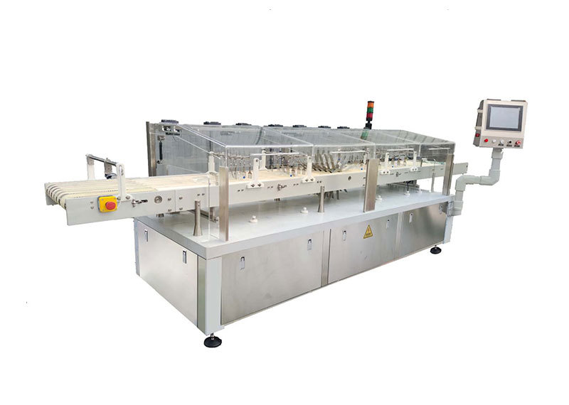
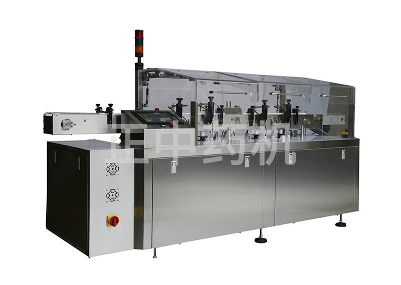
● Automatic inspection machine for particulate matter in ampoules
-
● Automatic inspection machine for oral liquid foreign objects
-
● Automatic inspection machine for lyophilized preparations in vials
-
● Automatic foreign object inspection machine for plastic bottle intravenous infusions
-
● Electronic microporous leak detector for ampoule injections
-
● Fully automatic electronic microporous leak detector for infusion
-
● Automatic foreign object inspection machine for glass bottle intravenous infusions
-
● In-line plastic ampoule electronic micro-hole leak detector
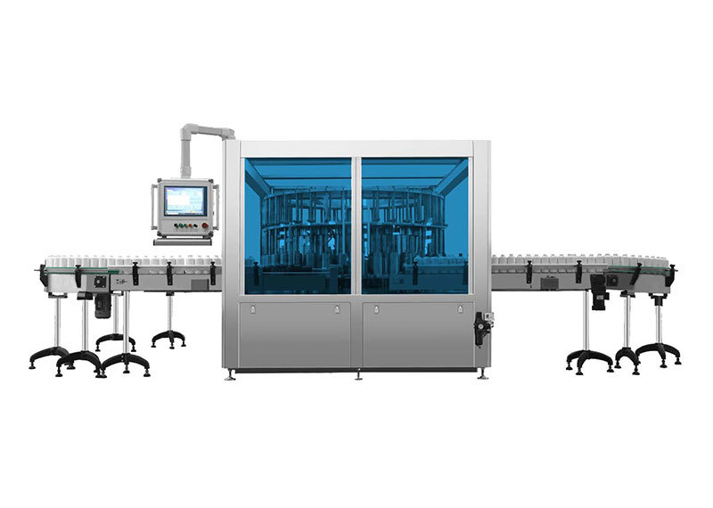
ZJL250 Vacuum Decay Leak Detector
Mainly engaged in the research and development of ceramic new material valves, with metal valves (gate valves, globe valves, ball valves, butterfly valves) as a secondary business. Ceramic valves have been successfully applied in many new energy battery material plants, thermal power plants, nuclear power plants, chemical plants, steel plants, coal chemical industry, polysilicon and other industries, and have been listed as special-purpose products, contributing to energy conservation and environmental protection for enterprises and society.
Category
Vacuum decay leak detector
Keyword

Details
Structural Principle
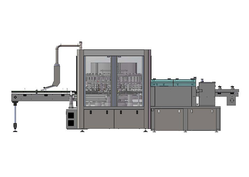
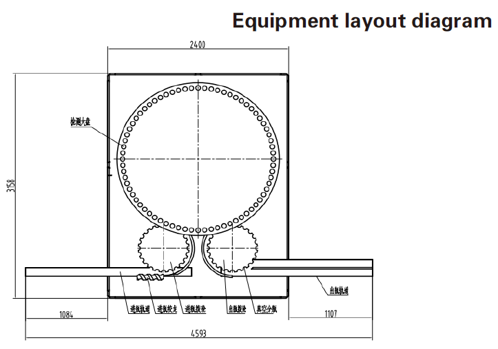
This machine mainly consists of a bottle infeed mechanism, a turntable inspection area, a bottle output mechanism, a bottle sorting mechanism, a frame, and a control operating system.
The bottles to be tested are fed via a track, sorted by an infeed auger, and then sent to the infeed wheel. The infeed wheel transports them to the test chamber in the turntable inspection area. After sealing the test chamber, a vacuum is drawn. The pressure difference between the inside and outside of the container causes the internal gas to enter the test chamber through leak holes. A pressure differential sensor connected to the test chamber monitors the pressure change, comparing it to the pressure of a leak-free container connected to the other end of the sensor. The magnitude of the differential pressure sensor value determines whether the container is leaking. After being tested, the containers move from the turntable inspection area to the outfeed wheel, and then to the outfeed auger, where a rejection device separates the qualified and unqualified products.
Workflow
The workflow is summarized as follows: Container to be tested → Infeed track → Infeed auger → Infeed wheel → Turntable inspection area → Vacuum decay leak detection → Outfeed wheel → Sorter separates qualified and unqualified products according to computer instructions → Qualified and unqualified products enter their respective outfeed tracks.
Equipment Layout Diagram
Main Features
- Uses differential pressure detection for high detection accuracy.
- Key components are made with CNC precision machining, and major outsourced parts are from well-known brands, ensuring stable and reliable equipment operation.
- Specifications are quickly installed and removed, greatly saving time for specification changes.
- Has fault alarm and display functions. When a fault occurs or improper operation is detected, the equipment will alarm or shut down. It also has a safety feature that stops the machine when the door is opened.
- Has a three-level permission function.
- Equipped with a UPS power supply to prevent data loss due to unexpected power outages.
- Has an audit trail function that records equipment operations and parameter changes.
- Inspection data automatically generates reports that can be queried, exported, or printed directly.
Mainly engaged in the research and development of ceramic new material valves, with metal valves (gate valves, globe valves, ball valves, butterfly valves) as a secondary business. Ceramic valves have been successfully applied in many new energy battery material plants, thermal power plants, nuclear power plants, chemical plants, steel plants, coal chemical industry, polysilicon and other industries, and have been listed as special-purpose products, contributing to energy conservation and environmental protection for enterprises and society.
Structural Principle
This machine mainly consists of a bottle infeed mechanism, a turntable inspection area, a bottle output mechanism, a bottle sorting mechanism, a frame, and a control operating system.
The bottles to be tested are fed via a track, sorted by an infeed auger, and then sent to the infeed wheel. The infeed wheel transports them to the test chamber in the turntable inspection area. After sealing the test chamber, a vacuum is drawn. The pressure difference between the inside and outside of the container causes the internal gas to enter the test chamber through leak holes. A pressure differential sensor connected to the test chamber monitors the pressure change, comparing it to the pressure of a leak-free container connected to the other end of the sensor. The magnitude of the differential pressure sensor value determines whether the container is leaking. After being tested, the containers move from the turntable inspection area to the outfeed wheel, and then to the outfeed auger, where a rejection device separates the qualified and unqualified products.
Workflow
The workflow is summarized as follows: Container to be tested → Infeed track → Infeed auger → Infeed wheel → Turntable inspection area → Vacuum decay leak detection → Outfeed wheel → Sorter separates qualified and unqualified products according to computer instructions → Qualified and unqualified products enter their respective outfeed tracks.
Equipment Layout Diagram

Main Features
- Uses differential pressure detection for high detection accuracy.
- Key components are made with CNC precision machining, and major outsourced parts are from well-known brands, ensuring stable and reliable equipment operation.
- Specifications are quickly installed and removed, greatly saving time for specification changes.
- Has fault alarm and display functions. When a fault occurs or improper operation is detected, the equipment will alarm or shut down. It also has a safety feature that stops the machine when the door is opened.
- Has a three-level permission function.
- Equipped with a UPS power supply to prevent data loss due to unexpected power outages.
- Has an audit trail function that records equipment operations and parameter changes.
- Inspection data automatically generates reports that can be queried, exported, or printed directly.
Previous Page
Next Page
Previous Page
Next Page
Related Products
Inquiry

